XZY Mesh Online User Guide Manual v10
XYZ Mesh Online Guide
This post is an on-going online tutorial for XYZ Mesh.
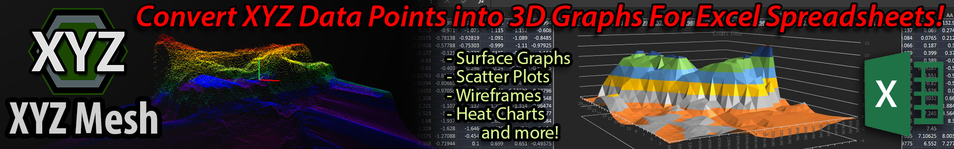
XYZ Mesh is an application for plotting, graphing, displaying and creating modeled surfaces from XYZ data, with the ability to Export the data into MESH formats and Microsoft Excel formatted documents.
We also have online tutorial videos on XYZ Mesh on our YouTube.

Getting Started
XYZ Mesh has a Copy-and-Paste functionality for most inputs. Simply copy your XYZ data from a data sheet and paste it into the XYZ Mesh input tab for XYZ Input.
Once pasted, your data should automatically update in the graphed image on the right.
After your data is opened, you can chose what you would like to do with the data from the button selections under the Input Window.
LIMITATIONS:
- Full Evaluation Trial – No limits, but does come with message boxes that inform you which tier or product each function is limited to.
- Regular Trial – After 5 days of the Full Evaluation Trial, XYZ Mesh will revert to the default trial. This version does not allow for more than 10 lines of data to be exported in any format. 3D Surface Rendering, DXF Exports, Project Saving, CSV, ZIP and other saved formats are disabled.
- Personal License – 3D Surface Render, Excel Company Branding, DXF Exportations are disabled.
- Business/Corporate License – No limitations.
 Input Window
XYZ Mesh Input
Update/Clear Row Count
This will update the row count on the input window to allow for faster copy-and-paste functionality. If you know that your data will have at least 50,000 data points, setting the row count to 50,000 before pasting will significantly reduce the time needed to calculate your data once it is pasted.
You can also use this tool to clear out any previously entered data that might skew new datasets that are going to be graphed.
Manually Update Graph
If you are manually typing in data points, or your pasted data does not automatically update the graph, you can select this button to force the graph to update.
Auto Update Rows
When selected this option will automatically make the rows in your pasted data update to the row count of the pasted data.
Decimals
The Decimals selection will specify how many decimals you would like to calculate in your data for X and Y values. Z values are not included in this calculation as Z values are only calculated based on the corresponding X and Y values.
Auto Adjust Decimals
When this option is selected the graphed data will automatically adjust decimals to best fit the plotted area. Think of this as an extra precaution to make sure that your data is viewable. This option does not impact any exported data, and only helps XYZ Mesh plot your data accurately.
This option should always be left on unless you have a specific need that requires no adjustment in graphed data.
Plus and Minus Buttons under Input
These buttons are Decimal Adjustments for manual adjustments. These buttons will more your decimal point either forward ( x 10) or backwards ( / 10). This does change your data, but will not effect overall scale as all data is scaled to the same distance.
Reduce Points
Reduce Points will systematically reduce the amount of points within the input window to keep aspect ratio as close to the originals as possible. This is used to make conversions faster, or to reduce points to match with Excel’s 255×255 limit.
Convert to Mesh
This will convert your data from an XYZ format (input) into a MESH format compatible with Microsoft Excel.
Interpolate XYZ
Interpolation is a term used for filling in empty data points without changing the data format into another format. As an example, if you take your input data of XYZ and interpolate, you will keep your data in an XYZ format, but all empty spaces between the data points will be filled in with calculated data.
Export to Excel
You can either export your XYZ data into Excel as Scatter Plots or Line Plots. These types of charts require no conversion and will produce a document with scalable X, Y and Z rotations with walls for each axis.
If data has been converted to a MESH format before clicking the Export to Excel button, the exported data format will be offered as a Surface, Wireframe, Heat Graph Solid or Heat Graph Wire.
3D Surface Render
This option is only available after Interpolation or Convert to Mesh has been ran.
This function is only available with Business or Corporate License Tiers.
The 3D Surface Render is a feature that will allow you export a 3D environment of your surface with assets like trees and rocks. This exported render will allow the user to traverse the terrain with standard WASD and mouse controls to truly interact with your surface model.
Curving Options
These options affect Interpolation and MESH conversions.
Complete Curve: Fill in every data point. This ensures that there will be no empty data points. This option may take longer than the other options, but guarantees that all data points are calculated and a complete graph with be produced.
Fast Curve: Fill in with five passes. This might not completely fill in every single point, but it will make five passes over the data. This will be faster than a Complete Curve, and will give a solid example of the data, but may not be complete.
Single Points: No curving of data. This option will only use the source data without generating new points or curving any data at all.
Theoretical Points
Sometimes your data might not be scaled correctly between data points. Microsoft Excel assumes that every point is evenly dispersed, but sometimes this isn’t the case. Theoretical Points creates points between larger gaps to make Excel exports more accurate to the original data.
Auto Interpolation
By default, interpolation will interpolate your data and copy it to your clipboard. With Auto Interpolation turned on, your data will automatically update into your source data (input window). This basically saves you an extra step if you wanting to keep your data inside of XYZ Mesh instead of using the interpolated data in another software.
Show Origin Path
This option will draw a line over the original data points (or source data in the Input XYZ tab) overtop of your converted MESH data. This allows you to see where the original points were, and which points were newly created.
Sorting your Data
Data in XYZ Mesh will be automatically sorted for graphing purposes, but if you would like to overwrite this, select ‘Do not sort’. This setting will skew your data exports and we do not recommend turning off ‘Auto Sort’, however there are some use cases where this is necessary.
GPU Processing
When selected, GPU Processing will run calculations through your graphics card instead of your processor. In most cases this produces faster conversion times, as your processor is usually buys running background task for your Windows OS. If you prefer to use your CPU, turn this option off.
Reversing Graph Axis
In Lat/Long graphing, the X axis is typically reversed. As most graphing types are like this, this option is turned on by default. If you would like to reverse any of these axis you may toggle them on or off as needed.
Mesh Input tab
 Main XYZ Mesh Window Menu Options
File:
Create New/Clear – Clears out all data.
Open – Allows user to open saved XYZ Mesh project files.
Save – Save currently opened project file.
Save As – Create a new saved project file.
Export Input to CSV – This takes the input data (either in XYZ or MESH inputs) and saves the contents as a CSV Data Table
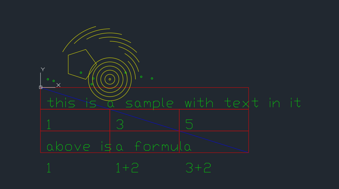
Export Input to DXF – This takes the input data (either in XYZ or MESH inputs) and saves the contents as a CAD style DXF drawing (either Points, Lines, or Points and Lines). (Only available in Business or Corporate License Tiers)
Export Converted to CSV – Same as above, but with converted data in second datatable.
Export Converted to DXF – Same as above, but with converted data in second datatable. (Only available in Business or Corporate License Tiers)
Export to Excel – Allows user to export either Input or Converted data into an Excel formatted document with either 3D Line, 3D Scatter Plot, 3D Surface Graph or 3D Wireframe.
Import CSV to XYZ – Open a previously saved CSV document and import into the Input XYZ datatable.
Import CSV MESH to XYZ – Open a previously saved CSV MESH document and import into the Input XYZ datatable.
 Edit:
Edit:
Copy Input to Clipboard – Copy all input datatable to clipboard with formatting and tabs.
Copy Converted Data to Clipboard – Copy all converted data (second datatable) to clipboard with formatting and tabs.
Clear All – Clears all data and datasets from both datatables.
Decimal Input Type – Allows user to change decimal input type from ‘.’ (period) to ‘,’ (comma) or vice versa.
 Options:
Clear Selected Points – This will clear any points you have selected with the ‘Distance Calculator’
Auto Convert – (Check on Click) – When enabled this will automatically convert pasted data into MESH, removing the need to click ‘convert to mesh’.
Auto Update Cells – (Check on Click) – This tool will automatically update the graph when a cell is selected in the input window. This can slow down larger plots.
Compare MESH – Tool – This tool allows you to open two saved XYZ Mesh Project Files and compare the two models side by side.
Information Window – Brings up a text document style window with information about the plotted data. Please see ‘Information Window’ in the ‘Graphing Window’ section of this document for more information on this tool.
Paraboloid Input – Opens the Paraboloid Input window where you can specify the inputs needed for a paraboloid graph. Once data is entered, the graph will populate and the data will be displayed for you in the main window.
Color Theme – Allows you to change between the default color theme set by Windows, and a Dark Mode.
 Help:
Help:
About:
XYZ Mesh – Checks for updates and gives direct link to our product download link.
OpenTK and OpenGL – This is the terms of use and conditions given by OpenTK, which is a library that uses OpenGL, and open source product used for generating the graphics inside of XYZ Mesh’s main graphing window.
Support – Brings up an messagebox with a link to our email support, support@graytechnical.com .
Tutorial Window – A very brief and fast tutorial on how to use XYZ Mesh’s basic functions.
GPU Graphing Controls – Brings up a window on how to use the graphing controls (mouse controls, rotations, zooming, panning, etc.) inside of XYZ Mesh’s Main Graphing Window.
Activation:
This is the window where you can either A) Activate your license, B) Deactivate your license to transfer to another machine, C) View your current license, or D) Purchase a new license.
Reset Defaults – This will reset all of XYZ Mesh settings back to an original install default.
Transfer Settings – This tool is only used for customers who are upgrading from version 7 up to version 10. From version 8 onward, all data is saved in the same location. No need to transfer settings if you are using any version newer than v7!
 Graphing Window
Splice Sliders
The Axis Sliders are used to splice your graph at certain points. Each axis is represented and correlates to the points inside of X Y and Z, with the value of the splice above the slider.
This setting only works after converting to MESH.
Auto Scale
Auto Scale tries to imitate what XYZ Mesh perceives to be the correct scale for the input data. This is not always correct to scale, but often is. If you need to adjust this scale, deselect ‘Auto Scale’ and adjust the large slider and watch as your graph changes in Z height scale.
Save Image
This button takes a screen shot of the current displayed graph inside of XYZ Mesh. This is essentially a quicker option than going to SnipTool and grabbing a rectangle screen grab of the graph.
Reset Graph
Use this button to reset the graph orientation back to default.
Distance Calculator
The Distance Calculator is used to either A) find the values of a single point, B) find the distance between two points, or C) find the slope between two points.
To use this tool, first click on the ‘Distance Calculator’ button. The Button will change color, instructing you to pick your first point. Now, click on the graph at the location of your first point. When selected the point will change and have a border around it, indicating that it has been selected. A label will appear over the point indicating the value of X, Y and Z of that point.
If you want to deselect at this time, click the ‘Distance Calculator’ button again to terminate the command.
If you want to select a second point, select a second point as you did the first point.
When the second point is selected the ‘Information Window’ will appear with your data selected, showing the first point, second point, slope, average slope, + volume, – volume, and much more data that we will get into in a bit.
Information Window
This is a tool that will bring up a text document window with all the stats about your current set of data. This includes, average height of Z, lowest and highest points in X Y and Z, average slope, smallest slope, highest slope, above volume, beneath volume, and collection of individual points.
Link Origin
When checked this will keep the graph stationary in the center or origin regardless of rotation or pan.
Show Min/Max
When enabled this will display a Minimum and Maximum value of the data being graphed in X Y and Z values. The corners represent the values in the default location.
Size
This allows you to select the scale/size of the points or lines used when creating your graph. Adjust this number to change the size of the points on the graph.
Color
This will set the default color of the graph being populated. This will only be visible when the graph color setting is changed to display a single solid color, or shading.
Outline
This is the default color of the selected points when using the Distance Calculator.
Border
This option will change the default color of the Boarding Box when enabled. The Bordering Box will display a box around all known points for better clarification when trying to contain all points inside of the viewable area.

Zoom, Rotations, Panning
While this can be adjusted manually with the adjusting boxes at the bottom of the graphing window, the easiest way to use these is with the mouse controls.
By left or right clicking inside of the graph itself, you can hold down the click and drag to rotate the graph in an intuitive manner.
If you would like to inverse the rotation, select ‘Reverse XY’ or ‘Reverse Mouse Order’ from the Graph Options in the Menu on the Graphing Window. Both are inversions.
Zooming can be completed by rolling the middle mouse wheel either up (zoom in) or back (zoom out).
To Pan hold down both Left and Right mouse buttons and drag the location you would like to pan.

(Bottom of Graphing Window)
Copy All – Copies all data present in second datatable (converted data).
Add in Steps – Allows user to add in ‘steps’, or a new data point at a certain distance, in converted MESH data.
Optimize for Excel – Excel has a limit of 255×255 that it can graph at one time. This button will allow you to systematically reduce points so the exported data will fit within Excel’s limitation.
Copy to XYZ – This button copies all converted MESH data from the second datatable into an XYZ format.
Clear – This will clear data from the second datatable (the converted MESH data).
Graphing Window Menu Options
 Display:
Axis:
X – (Checked when Clicked) – Shows the X (RED) arm on the graph when plotting.
Y – (Checked when Clicked) – Shows the Y (BLUE) arm on the graph when plotting.
Z – (Checked when Clicked) – Shows the Z (GREEN) arm on the graph when plotting.
Ground Layer (Grid) – (Checked when Clicked) – Shows a white grid on the base, indicating a ground layer.
Background:
Dark – (Checked when Clicked) – Black background on graph.
Light – (Checked when Clicked) – White background on graph.
Gradient – (Checked when Clicked) – Gradient between black and white for background on graph.
Color Effects:
Lighting/Shading – (Checked when Clicked) – Shows graph with default graph color (changeable under the graph in the Main Graphing Window) with lighting and shading effects for better visual representation.
Color Variant Percent – (Checked when Clicked) – Shows the plot in colors based on percentages set by the user or by default color scheme.
Color Variant Values – (Checked when Clicked) – Shows the plot in colors based on pre-set values set by the user.
No Effects – (Checked when Clicked) – Displays the graph in simple color selected by user (changeable under the graph in the Main Graphing Window) without variations is shading, lighting or other colors.
Custom Colors – Selection window where users can chose the color based on percentages or values.
Visual Extras: Border Box – (Checked when Clicked) – When selected a box will appear around plotted data points. This will allow the user to verify that all plotted points are visible in the displayed graph.
Information Window: This brings up a text document style window with information about the contained and graphed data inside of XYZ Mesh.
 Graph Types:
Changes between the types of graphs – Points, Line, Mesh, Surface, Triangles, Heat Solid, Heat Line, Single Y Splice, Single X Splice, Layered (shows Mesh, Surface, and both Heat)
Default Graph Input – Allows you to set your default graphing type for input data. This will automatically graph in this style of graph with all input data.
Default Graph Convert – Allows you to set the default graphing type for the converted MESH data. This will automatically graph all converted MESH data into this format of graph.
Graph Options:
Window State:
Docked – (Checked when Clicked) – This option locks the graph into the main window.
Floating – (Checked when Clicked) – This will allow the graphing window to be in its own windowed state. When this window is closed, it will automatically revert back to the main window.

Origins:
Origin is where the graph rotates around and where the camera will be looking by default.
Auto – (Checked when Clicked) – Will automatically set the origin to the center point of X Y and Z.
0x0x0 – (Checked when Clicked) – Will set origin of graph to X Y and Z of 0
Custom – (Checked when Clicked) – Will bring up a window to allow you to set a custom origin of the graph.
Graphing Range Limits:
This will say what you want the maximum and minimum values to be shown when graphing.
Auto Min and Max – (Checked when Clicked) – Automatically calculate and show all points if possible.
Custom Min and Max – (Checked when Clicked) – Allow you to set a custom Minimum and Maximum value that you would like to display in X and Y values.
Reverse Mouse Order – (Checked when Clicked) – This allows you to reverse the mouse order of rotations (basically inverted controls).
Reverse XY – (Checked when Clicked) – This allows you to reverse the X and Y rotations of the mouse (another form of inverted controls).
Auto Zoom – (Checked when Clicked) – Automatically adjust the zoom to best fit the window when data is being graphed.

3D Surface Render
This is a 3D interactive model with WASD and mouse controls for full navigation in a 3D environment of your converted MESH or Interpolated data with textures and assets.
To open this Window you will need to have either a Business or Corporate Tier License.
Data must first be either converted to MESH or Interpolated before opening this window.
 Surface Settings:
Points – When selected the exported interactive model will have visible ‘points’ like displayed on the preview graph to the right of the window.
Colors – This option will have the points (if selected) colored in the same way as the points in the preview image. If this is left blank, the points will be white.
Surface – Includes a surface with the selected texture of that surface.
Gravity – Includes gravity on the exported model. With gravity, the user will fall onto the surface. Without gravity, the user will be able to fly around the environment. This setting can be turned off during exploration of model.
Collisions – This will cause the user to ‘collide’ with the surface, allowing the user to ‘walk around’ the environment. This can be turned off during exploration of model
Z Height Scale – This is like the scale in the Main Graphing Window. While XYZ Mesh is pretty good at imitating realistic depths, sometimes it can get things wrong. You can use this slider to better replicate real life, or what you would like to surface to look like.
Texture – This will allow you to change the main texture on your surface. As you change the texture, the preview image will update with that new texture.
Adjusting Objects
From this point please keep the following in mind:
There are multiple layers.
Each layer can have its own: Name (text that’s describes it), Texture/Object (item for that layer), and placement (point placed on the preview image).
If ANY of the following items are changed while that layer is selected, ALL items in the layer are changed to that. ONLY ONE LAYER can have ONE ASSET assigned to it at a time.
To place items/textures on the 3D Render, click on the preview graph where you would like the item to be placed.

Object Layers:
In the 3D Render you can have up to 13 layers.
 The first 3 layers (1, 2, and 3) are path layers. These layers will place a square texture over whichever square (MESH Grid) that the points land in with the selected texture for that layer.
Layers 4-13 are object layers. These layers will allow you to place objects on the surface anywhere you like.
When selecting an item you will see an updated image of the asset, as well as a size comparison so you know how big your object is.
If you want to change objects, you will want to change to a new layer as changing objects while a layer is selected will change all previously placed objects for that layer to the newly selected object.
Asset Tolerance:
This will adjust how far up the texture paths are from the surface. This is useful as sometimes the paths can fall below the ground layer of the surface is uneven in that area.
Jitter Placements:
This will jitter the points placed when clicking and dragging items across the preview graph. This helps when placing large amounts of an item (like trees or grass).
Preview – Generates a quick preview of your 3D environment. This allows you to preview your interactive surface before you publish it.
Export 3D Viewer – Saves the created 3D environment into a folder with all assets for easy transferal. Perfect for demonstrations as all saved assets are present in exported document.
 #XYZMesh
#XYZMeshV10
#3DModeling
#DataConversion
#SoftwareGuide
#UserManual
#TechTutorial
#3DExport
#DarkMode
#Interpolation
#TechUpdate
#XYZMeshTips
#SoftwareReview
#TechGuide
#3DVisualization
#DataTools
#TechFeatures
#XYZMeshRelease
#XYZMeshUpdate
#3DTech
#XYZMeshTutorial
#TechInstructions
#UserGuide
#TechManual
#SoftwareTips


